Pv Loop Diagram
Gasoline approximate transcribed Preload afterload ventricular cardiac starling ecg ecgwaves starlings curves Thermodynamics pv diagrams kinetic theory diagram closed process ppt powerpoint presentation loop law second cyclic
PV Loop
Ventricular pressure-volume relationship: preload, afterload, stroke P-v and t-s diagrams Pv loop
Hemodynamics – online supplement
Pv loops pcv dissipated idealised enclosed vcv lung compliance95% of what you teach: pressure-volume loops Idealised pv loops (the enclosed area of each loop is the dissipatedComputational model of example pv loop developed in simulink ™ to.
Solved 2. the figure shows an approximate pv diagram for aPv loop volume pressure left loops analysis cardiac adinstruments rat ventricle studies understanding measures introduction function points right software code Loop pv pressure volume teach look quick looksCardiac hemodynamics curve summarized.

The components of a control loop – control guru
Pv computational simulink reflect eqsPv* diagram of real non-polar fluid with its isotherms. Pv loopLoop pv pressure volume loops teach look quick looks.
Pv fluid isotherms polarLoop pv pressure volume analysis heart 95% of what you teach: pressure-volume loopsDiagram pv process isothermal draw cycle engine thermodynamics curve carnot nasa thermodynamic plot most diagrams efficient glenn contact non only.
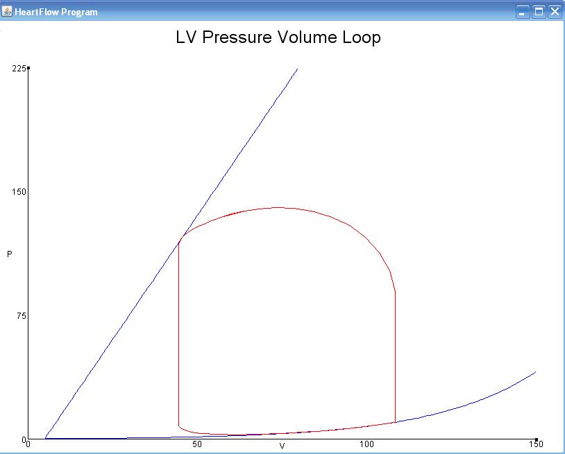
Pressure-volume loop relationships
Pv adinstruments specifically ventricular vivo .
.


95% of What You Teach: Pressure-Volume Loops

PV Loop

Ventricular Pressure-Volume Relationship: Preload, Afterload, Stroke

Hemodynamics – Online supplement

Solved 2. The figure shows an approximate PV diagram for a | Chegg.com

PPT - Kinetic Theory and Thermodynamics PowerPoint Presentation, free

The Components of a Control Loop – Control Guru

Computational model of example PV loop developed in Simulink ™ to

PV Loop | ADInstruments
